The Motivation
Electronics labs at our universities and workplaces can have good sides and bad sides. Mine, for example, is filled with great equipment and knowledgeable people. However, it has a sum total of zero windows to the outside world. Occasionally it is nice to work on side projects at home at your own leisure. As a graduate student, funds for personal electronic equipment aren’t always plentiful so I’m trying to outfit myself with as much homemade equipment as possible. This is the start of what I’m hoping will be several posts about that process. I’ll be starting with one of the most basic pieces of equipment an EE needs, a power supply.
The Supplies
We’re going to be starting with a desktop computer power supply and convert it into something more friendly for electronics work. They look something like this:

Mine was salvaged out of one of those black Dell computers that universities like to buy (and later throw away) by the dozens. Inside they have a fan, transformer, regulator and some accompanying circuitry, and a rainbow of wires leading to some Molex connectors.
Warning: The power supply contains two very large capacitors that can hold a charge for long after the unit is unplugged. Let the power supply sit unplugged for several days before trying to open it up.
We’ll be wiring in 5 binding posts, 4 for our regulated voltages and 1 for ground. Sparkfun sells individuals for a few cents. I made each of the voltages red and the ground black. You can also choose different colors for each of the regulated voltages.
I also used an SPST switch I had laying around (I’m pretty sure I bought it from RadioShack at one time) as well as an LED and accompanying resistor as an indicator. You’ll also need a 10Ω 10-Watt power resistor to ensure our supply operates correctly.
I also gathered some other supplies for the build:
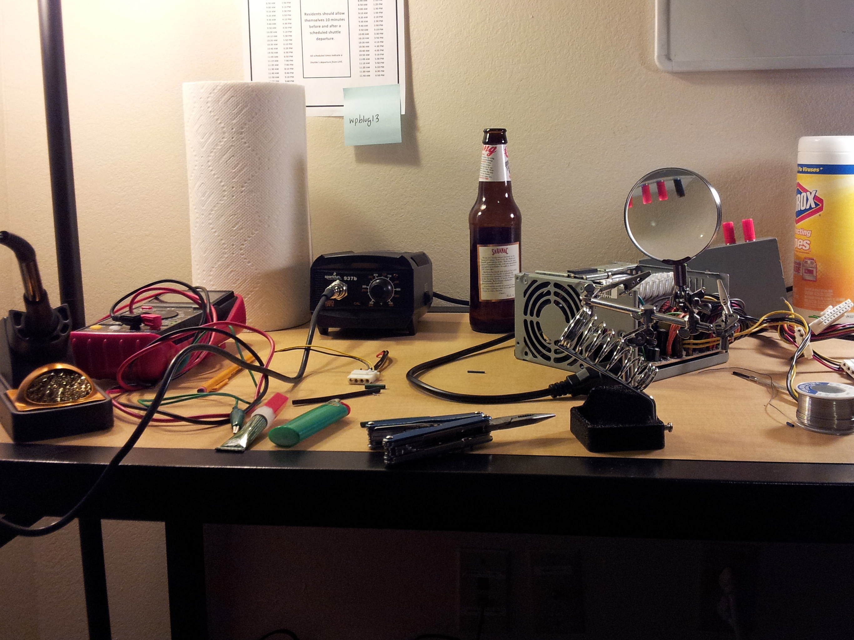
- Soldering Iron and Solder
- Solder Helping Hands
- Multimeter
- Superglue
- Heat Shrink Tubing
- A Good Beer (not required, but highly recommended)
The Build
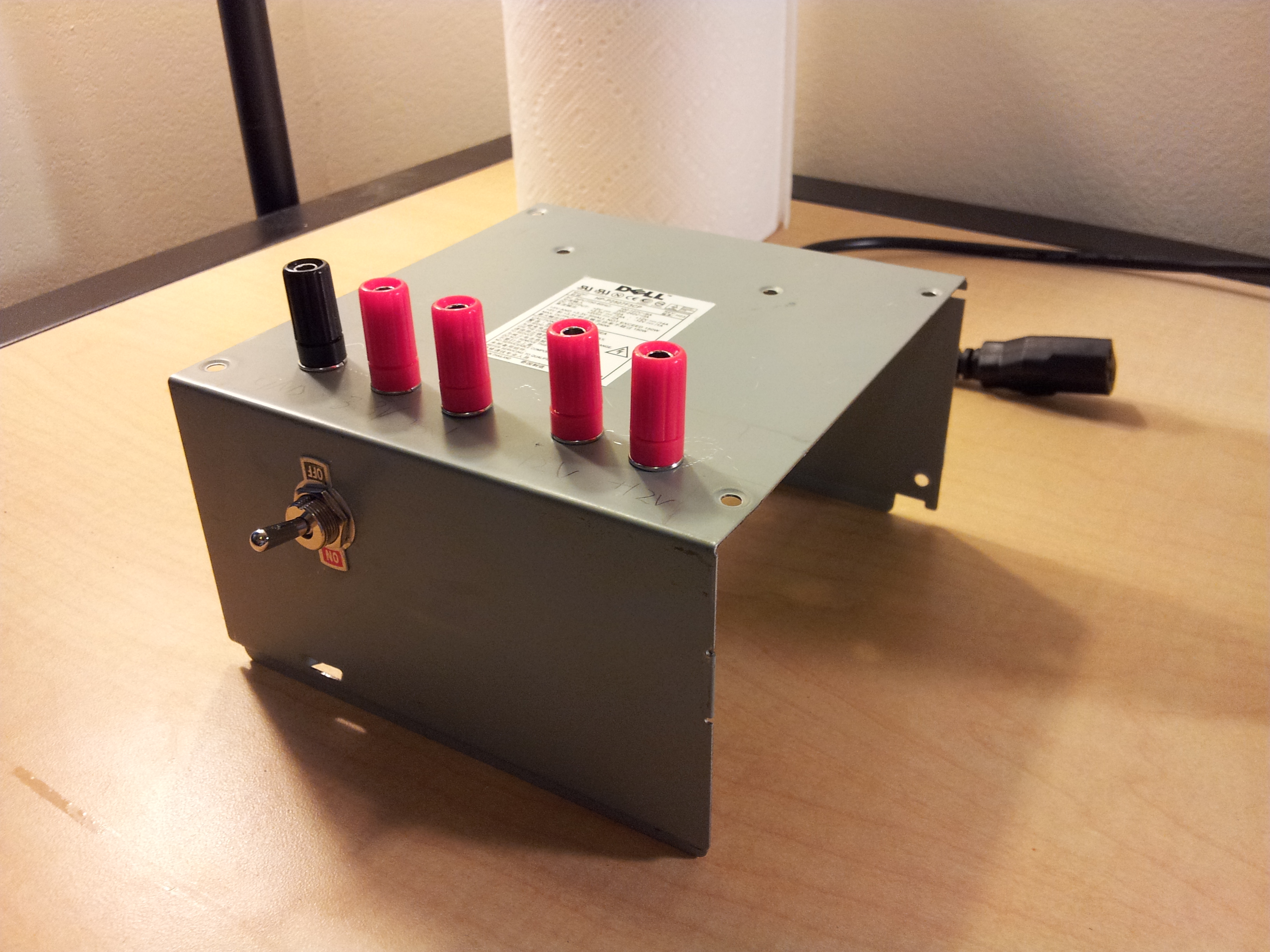
The first order of business is mounting the binding posts. I drilled five holes in the top of the power supply case. The posts pop right in and are held in place with a washer and nut. Next, a hole for the switch is drilled in the front of the case and the switch is mounted. Be sure to position the switch such that the case fits back on the power supply without bumping into anything.
Inside the power supply there will be many different colored wires. Most of these power supplies have a standard color scheme, but make sure to check with a multimeter to make sure yours follows it:
- Orange: 3.3V
- Red: 5V
- Yellow: 12V
- Blue: -12V
- Black: Ground
In addition there will be three additional wires:
- Green: Turns on the supply when shorted to ground
- Purple: Puts out +5V when the supply is plugged in and off
- Gray: Puts out +5V when supply is plugged in and on
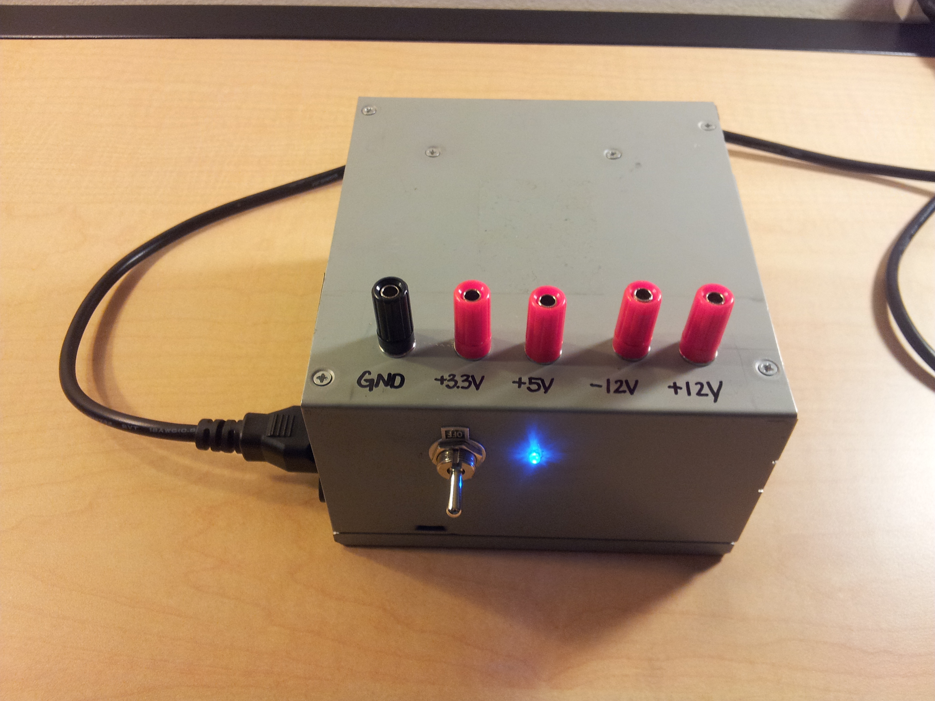
We’ll connect one terminal of an SPST switch to Green and the other terminal to ground. When the switch is closed the power supply should turn on. The purple wire won’t be used, but could possibly drive a second LED to let us know that our supply is plugged in but the switch is off. The gray wire will be connected to our status LED that shows the supply is on and running. Connect the gray wire to a resistor. Connect the resistor to the anode of an LED and connect the cathode to ground. The value of the resistor can be sized depending on the LED voltage drop and current maximum. I used a 330Ω resistor which might have been overkill for a blue LED with such a high voltage drop, but we don’t need the LED to be very bright.
There’s one more thing to add to the case. Most of these power supplies expect a certain minimum load while they’re operating. If there’s no load on the supply sometimes the ±12V rails won’t be regulated to the correct voltage. In order for the power supply to behave properly we’ll connect a 10Ω resistor to the 5V rail to give the supply a constant load. Since there will be quite a bit of power dissipated through this guy, I chose a 10-Watt sandbar resistor. The resistor is superglued to the side of the case and connected between 5V and ground.

The step is fairly straightforward. Solder the four regulated voltages and the ground to the binding posts we attached to the case. We only need one wire per voltage so we can get rid of the rest to save some room inside the case. We could desolder them all from the board but I found that cutting them off was much easier. If there is any exposed metal where the cuts have been made we can cover the ends with a small bit of heat shrink to prevent any accidental shorting.
 Before plugging the supply in check that all the connections have been made correctly. Wrap all connections between wires or use heat shrink to make sure nothing is exposed. When the device is first plugged in all the posts should be at 0V. When the switch is turned ON the LED should light and each post should read the correct voltage. Each post should be labeled. I used a few zip ties to tame the remaining wires and put the case back on the unit. The wires should fit nicely in the space in the front of the unit.