
I recently picked up an Arduino Uno from Sparkfun with my last order. For years I’ve been using the MSP430 Launchpad as my microcontroller of choice mostly because they’re incredibly cheap and low power to boot. The Arduino and it’s user-friendly libraries make it easy to throw together a project very quickly.
That is exactly what I needed when I found myself the night before Halloween with no costume ready for the next day. Luckily I had almost all the materials I needed to build my Arduino-Powered Xbox 360 costume. With a little programming the “power button” lights up and flashes to mimic the Xbox 360 power up sequence. This project exemplifies the phrase “quick and dirty” but I think produced a good result!
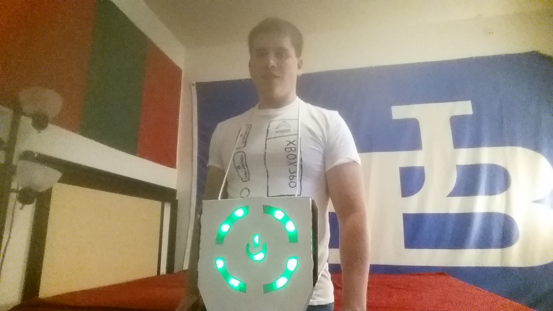
The Finished Product
The Supplies
I already had most of the components used in this build, the rest were easy to find at my local Radio Shack. Everything should also be readily available online.
Electronics
- Green LEDs (x10)
- 150 Ohm – 200 Ohm Resistors (x5), anywhere in that range works
- NPN Transistors (x5) in TO-92 package such as 2N2222 or 2N3904
- Arduino Uno
- Protoshield for Arduino Uno, essentially just a big piece of perfboard with headers that plug into the Uno
- SPST switch. I found this cool one at RadioShack.
- 9V Battery Connector
- 9V Battery
- Assorted hook-up wire
Materials
- Pizza Box. Dominos should give you one for free if you ask nicely.
- Nylon Cord (what I used) or any type of thin rope.
- Wax Paper, to diffuse the LEDs
- White Paint
- Plain White T-shirt
The Circuit
There are five segments to the power button. The center with the power logo and four quarter circle sections. Each is controlled separately by the Arduino. Each segment has two LEDs, though adding more LEDs is definitely a possibility.
The power supply for the circuit is a 9V battery. Each LED has a voltage drop of about 3V. I bought my LEDs in bulk on eBay, so I don’t have any exact specifications on the maximum current rating, but I would guess it’s in the neighborhood of 20mA. That means there must be a 150 Ohm current limiting resistor in line with the LEDs. I only had a few 150 Ohm resistors so I used 200 Ohm for a few of the LED segments, better to allow too little current than too much.
Furthermore the LEDs need to be switched on and off using the 5V I/O pins of the Arduino. For that an NPN transistor operating in saturation mode is used as a voltage-controlled switch. There will be five copies of this circuit, all tied into different pins of the Arduino.

LED Circuit
The last part of the circuit needed is a power switch. This will be tied in series with the battery to turn the Arduino on and off. The other end of the switch is soldered to the VIN port of the Arduino which can handle a supply voltage in the range of 6V-20V.

Switch Circuit
The Build
I started with a medium-sized pizza box for the housing.

I then cut out the center and four sides


In order to wear the box I added a length of Nylon cord tied in a loop. I threaded this between two holes cut on the top of the box. I also threaded another length of cord through the back so I could tie the box to my waist and prevent it from flopping around. Lastly I painted the box with some white paint.

The circuit was put together on an Arduino protoshield, I picked up one made by Seeed Studios but there are quite a few out there. The shield comes with pin headers that fit the Arduino Uno.

I assembled the transistors and resistors on the protoshield. The base of each transistor is connected to a pin on the Arduino through a piece of jumper wire. A resistor is connected between each emitter and a point on the board where wire leading to the LEDs will be attached.

Not The World’s Cleanest Layout, But It Works
I then wired in the battery snap connector and push button switch. The button turns the Arduino on/off by connecting/disconnecting power to the VIN pin. I gave the switch about two feet of wire so I could feed it out the side of the box and tuck it away in my pocket.

I then needed pairs of two LEDs that could be positioned inside the box to light up each segment. I ended up cutting a few rectangles of cardboard, poking two holes through each, and taping two LEDs in place. The LEDs were connected to the board with some spare wire and heat shrink.

I wanted each section to be lit up as smoothly as possible. The LEDs I got do a good job of lighting up the area directly in front of them but don’t allow much light out their sides. I wanted to light up each section as smoothly as possible so I took an extra step to help the light diffusion. I used some fine grain sandpaper (about 400 grit) to rough up the plastic housing around each LED. This helped quite a bit to diffuse more the light to the surrounding section

With five LED sections made I just needed to tape them down in the correct spot in the box and connect each to the proper place on the protoshield. I programmed a quick Arudino sketch to turn on all the LEDs to make sure everything worked.

Lots of Duct Tape
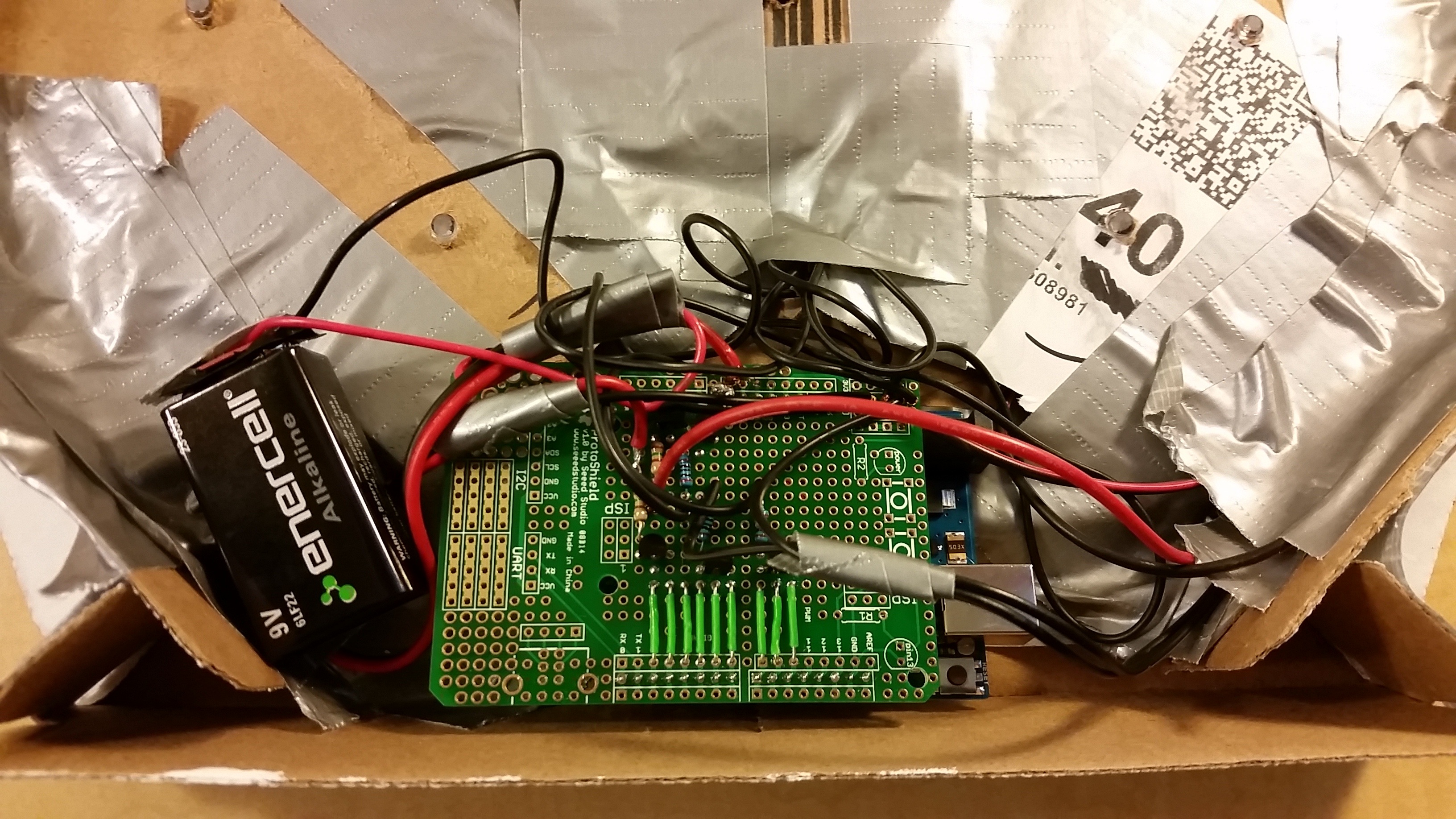
Close Up Of The Arduino In Place
The last step of the box assembly was to tape a few sheets of wax paper on the inside of the lid of the box in order to help diffuse the LEDs and better hide the wiring and tape on the inside.


Side View With Switch
The Software
I connected each quarter circle to a digital I/O pin on the Arduino. The center LEDs were connected to a PWM pin which allowed me to control the brightness. This was used to make a fade in and out effect for the center button.
The code runs through a set of functions to mimic the Xbox 360 startup sequence. Mostly this was just flashing various LEDs. To create the “chasing circle” effect the Arduino flashes the quarter circle sections one after the other for several revolutions around a circle.
The main loop switches between running the startup sequence, waiting with the “Xbox” on, turning everything off and waiting, fading the center LED, waiting, and running the startup sequence again. The delays make it so that your costume isn’t constantly flashing in peoples’ faces. It’s also cool when someone initially doesn’t realize the costume lights up and then it starts flashing like crazy.
The Arduino code is available on GitHub.
Finishing Touches
The last thing I needed to sell the costume was the rest of the Xbox. I used a sharpie and a blank t-shirt to draw out the rest of the front and back of the Xbox.


All that is needed is to throw on the shirt and pizza box power button and press the switch. The project looks okay in well lit rooms, but even better in the dark! Check out the completed project in action below.

Pingback: Using Arduino and Python to Monitor #TheButton | Adam Gannon