I’ve been working quite a while on a piece to hang up on my wall that displays – in real time – which spacecraft are communicating with NASA’s Deep Space Network. I finally got the prototype working and am excited to share the build process.
Background
It is amazing that we humans can communicate with our robotic explorers across distances greater than the solar system itself. Voyager 1, now in interstellar space, is so far away that radio signals – traveling at the speed of light – take 22 hours to reach the probe and its responses a further 22 hours to return to us. As part of my job in the space communications field, I sometimes interact with NASA’s Deep Space Network (DSN). Headquartered at NASA’s Jet Propulsion Lab in California with major ground station sites in Spain and Australia, the DSN is responsible for communication with dozens of spacecraft across the solar system and (in the case of the Voyagers) beyond. This year I had the chance to see their impressive operations center.
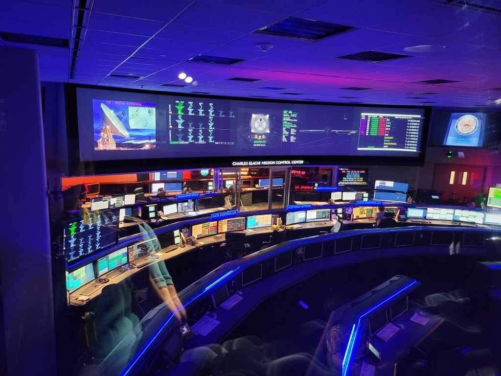
DSN also operates a very neat website which displays spacecraft that are communicating with each antenna – all in real-time. The display differentiates between carrier versus modulated data for both uplink and downlink.
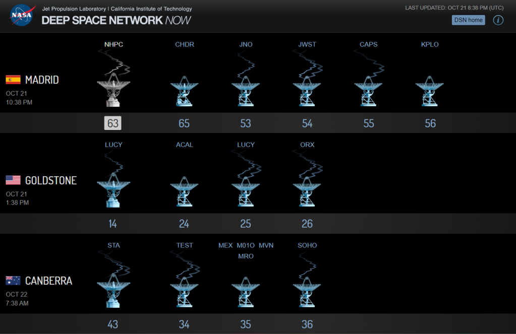
What if, I thought, the information driving the website could be used to power a physical display to show the status of my favorite spacecraft in real-time? I would use LEDs to light up an image of each spacecraft while it was currently communicating. This could be hung on a wall and constantly run in the background as a neat reminder of our amazing capability to communicate across vast distances.
Hardware
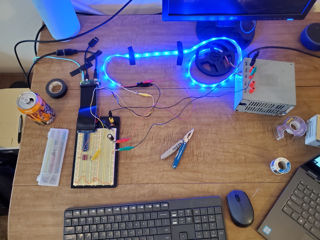
After the adventure of wiring 26 individual LEDs for my Stranger Things Halloween costume I knew I wanted to make things simpler with addressable LEDs. A strip of Adafruit’s NeoPixels were great for this. The strip has only three pins to wire: 5V, ground, and data. The data line connects to the controller chip inside each LED to command brightness and color.
I also decided to try a RasPi-based solution this time instead of using a microcontroller. The hardware timing wasn’t critical (plus Adafruit supplies a great Python library for NeoPixels that is Pi-compatible) and I’d benefit from having a full operating system to retrieve and parse data from the DSN. I went with the RasPi Zero W, a cheap model with a full WiFi stack built in. I also grabbed a GPIO breadboard breakout from Adafruit to help with prototyping.
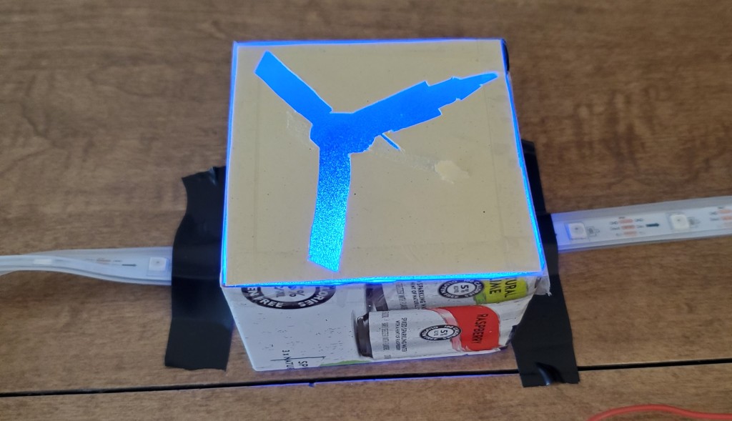
Rather than antenna-centric as the website, my build would pick several spacecraft and light up their silhouettes when active. After some quick prototyping, I landed on cutting the silhouette out of opaque material and using frosted vinyl (the kind you get to turn normal glass into a privacy window) to diffuse light from the individual LEDs. I found a good ratio was to have three LEDs illuminating a spacecraft image about 2″ wide.
Though the Pi is doing most of the heavy lifting, there are a few housekeeping items to take care of in the circuit:
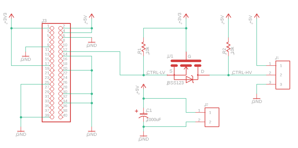
- I will be powering the strip and Pi with a 5V wall wart, but the Pi GPIO logic level is 3.3V. I’m using a Sparkfun logic level converter in the breadboard to step up the Pi’s 3.3V logic to the 5V which the NeoPixels expect.
- The manufacturer recommends a large (1000μF) capacitor across the power supply and a 300-500Ώ resistor inline with the data pin.
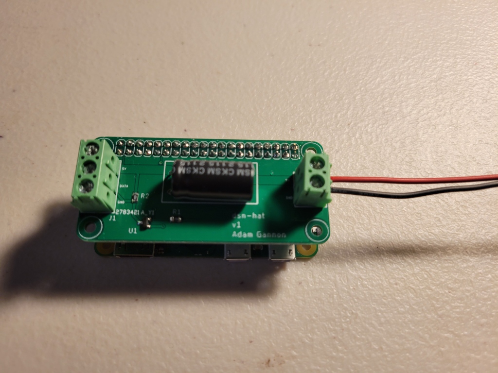
With the circuit working on a breadboard I created a PCB design which includes these components plus some screw terminals to connect the NeoPixel strip and a barrel plug for power. I implemented the same circuit as the Sparkfun logic level converter directly on the board with its component parts (a BSS123 MOSFET and some resistors).
The board is shaped to be the same size as the Pi and connect through the 40-pin GPIO header. These application-specific boards that nest on top of a Pi are commonly called HATs. I sent the build to JLCPCB, who spun five boards for about $6 with shipping.
Building The Frame
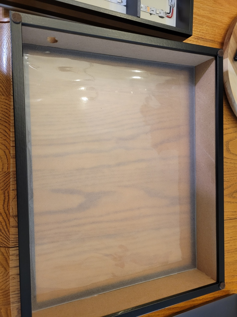
For the frame itself I got a shadowbox off Amazon. These are typically used for displaying items but I would use some foamboard to build up individual sections for each spacecraft’s LEDs. I started off by drilling a wide hole in the bottom of the frame to mount a barrel jack for power. A sheet of frosted vinyl was cut to cover the pane of clear glass for light dispersion.
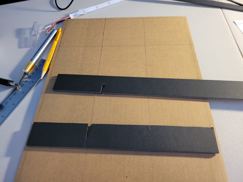
I cut some foam board into strips and notched it to build up a 3×4 grid to hold twelve spacecraft. Having a thick material as a divider was a must so light didn’t bleed over and illuminate adjacent spacecraft boxes.
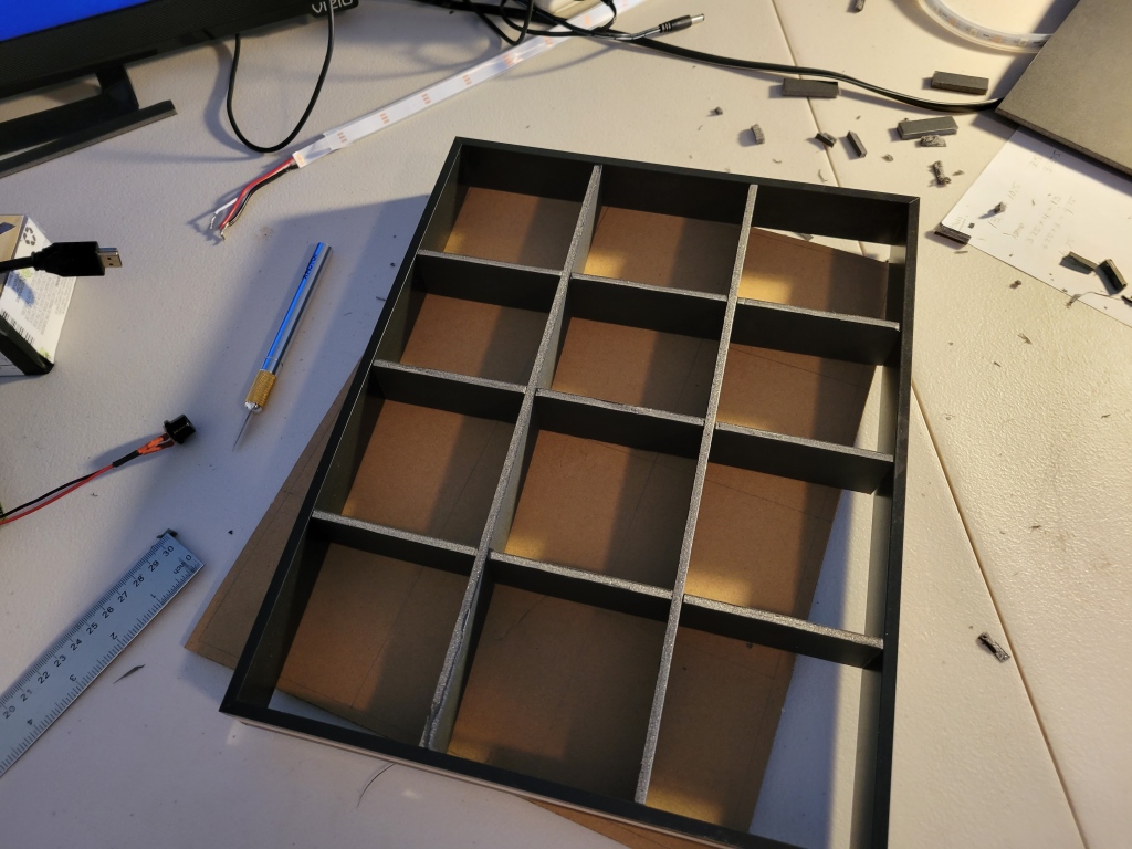
Unfortunately I had to give up two squares so I could mount the Pi in the frame. If I did this again I’d probably resize the grid to leave a more narrow space to fit the computer. I sunk some standoffs into the thick cardboard backside of the shadowbox. This gave the Pi a very secure mounting.
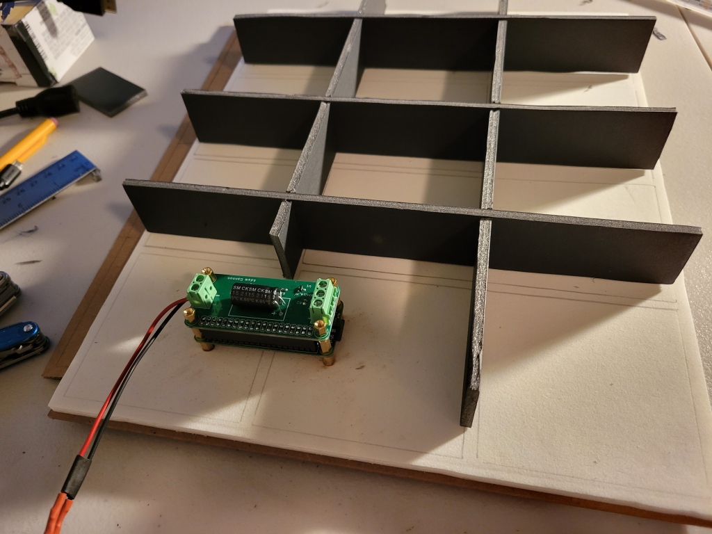
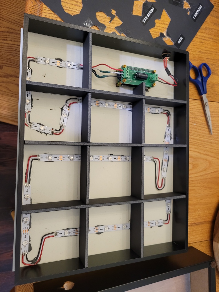
Now it was time to mount the LEDs on the backing. I didn’t do a great job taking into account the spacing between LEDs when designing the grid. This required some bends and jumper wires to fit exactly three LEDs in each space while still tracing out the grid. The layout is basically the polar opposite of Design for Manufacturing, but it gets the job done. My glue gun was acting up when I went to tack down the LED strips so I went for the nuclear option of JB Weld epoxy. Those strips will be attached to this thing forever.
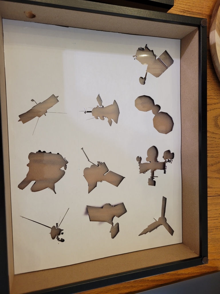
Finally I needed the silhouettes themselves. I grabbed images from NASA looking for spacecraft that will be flying for a while and had an outline that looked easy to cut out. These were printed on a large sheet of paper at the proper scale. I taped the stencil to a sheet of black posterboard and cut out each spacecraft shape. In the future I’d like to experiment with a CNC for this portion, but an X-Acto knife did the job pretty well. This sheet was layered behind the glass and vinyl. I printed some clear labels to identify each spacecraft.
Software
Step one for the code was to parse data on the DSN website. A super helpful start was Russ Garrett’s GitHub repo which powered the @dsn_status Twitter bot before some API changes broke it a while ago. With only a few changes, I used a version of the module to parse the site’s XML into a nested dict.
Data on the DSN site is organized by antenna. Each antenna has status on its uplink, downlink, and the target spacecraft (in some cases a single antenna can receive signals simultaneously from multiple spacecraft within view). Each time the main loop runs, I iterate through the antennas and find the antennas which are communicating with the 10 spacecraft on the board. From that antenna I pull its uplink/downlink status.
 # Init a dictionary from our spacecraft list to hold parsed status.
 sc_update = dict.fromkeys(hardware.spacecraft, Status.OFF)

for ant in data.keys():
    # Get targets (can be multiple). Filter out
    # any targets that aren't on the board
    targets_raw = list(data[ant]["targets"].keys())
    targets_low = [x.lower() for x in targets_raw]
    filt_targets = [x for x in targets_low if x in hardware.spacecraft]

    for spacecraft in filt_targets:
        status = calc_status(data[ant])
        sc_update[spacecraft] = status
I defined a set of colors for each possible status. The both options are set if both the uplink and downlink are in the same mode (e.g. carrier or data). Each tuple is a red, green, blue (RGB) triplet that defines the intensity of each primary color in the LED. If the spacecraft is not found on the active list, the default status is off. I went for a blue/purple color scheme, but this can be easily reconfigured if I want to switch it up.
class Status(Enum):
    """RGB triplet for each type of spacecraft status."""
    OFF = (0, 0, 0)
    UP_DATA = (0, 235, 145)
    DOWN_DATA = (0, 130, 235)
    BOTH_DATA = (225, 0, 235)
    UP_CARRIER = (0, 0, 235)
    DOWN_CARRIER = (0, 0, 235)
    BOTH_CARRIER = (0, 0, 235)
The final step is to update the LEDs. I defined a hardware mapping dict which specifies which LEDs correspond to each spacecraft silhouette. Using this I can set the LEDs for a spacecraft to the RGB value set by the current status. I wrap this in a helper class, but the NeoPixel library does the heavy lifting to communicate with the LED controller chips.
class Leds:
    """Manipulate LEDs."""

    def __init__(self):
        self._pixels = neopixel.NeoPixel(board.D18, 30)

    def set_group(self, pins, status):
        """Set each pin in the list pins to the
        RGB triplet contained in status."""
        for pin in pins:
            self._pixels[pin] = status.value
            logger.debug(f"LED #{pin} to {status.value}")
Finally, a few housekeeping things. Execution of the loop only takes tens of milliseconds so a sleep every loop prevents me from hammering NASA’s website. Contacts are tens of minutes, so this can be a fairly lengthy sleep and not miss much updating. I also don’t need the LEDs on all the time, especially when I’m sleeping. This was the first time I exercised argparse’s ability to accept a custom function as a type argument. Here I’m having it convert a string time window into a pair of datetimes. When the RasPi’s system time is outside this window I turn off the LEDs.
  def main():
    # Set up argument parser
    parser = argparse.ArgumentParser()

    # Allow operation within a time window.
    default_window = parse_time_window("08:00-22:00")
    parser.add_argument("--window", type=parse_time_window,
    default = default_window,
    help = "Time window to display LEDS in 24 hour HH:MM-HH:MM format.")

def parse_time_window(input_str):
    try:
        start_str, end_str = input_str.split('-')
        start_time = datetime.strptime(start_str, "%H:%M")
        end_time = datetime.strptime(end_str, "%H:%M")
        return start_time, end_time
    except ValueError:
        raise argparse.ArgumentTypeError("Invalid time window format.")
With the code complete, I packaged it up as a pip-installable package dsn-leds. Adding this to /etc/rc.local will start the script on boot, where it will run indefinitely.
Testing & Mounting
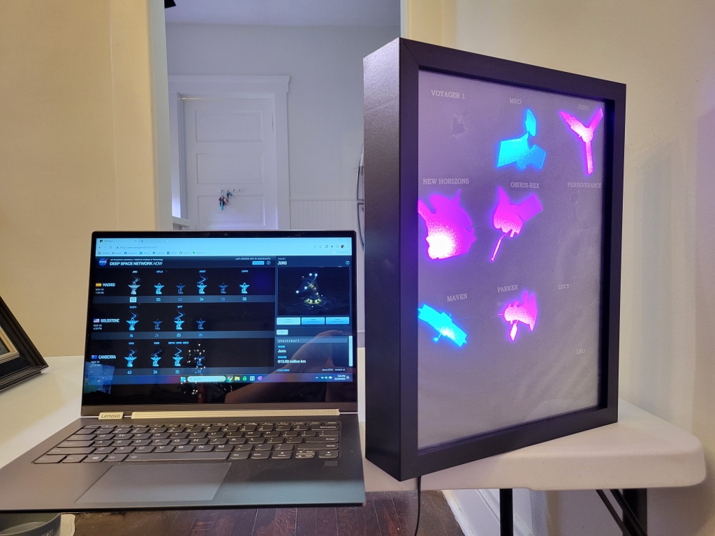
With the code complete I can check against the DSN website to verify everything is working. In the screenshot taken below there are 11 spacecraft listed:
- Maven and MRO are in downlink data mode (blue on board).
- Juno, New Horizons, Parker, and OSIRIS-REx are sending data bidirectionally (purple on the board).
- James Webb, Mars Odyssey, Kepler, and CAPSTONE are active but these spacecraft are not on my board.
- DSN is used for testing, per the website.
And it looks pretty good mounted on the wall!

Full code for this project is available on my GitHub.
