I learned from my girlfriend, a self-described plant person, that I’ve probably killed most of my plants from giving them too much water rather than not enough. However, our plans to be out of town for several weeks were going to be too long for her several houseplants to go without water. My solution: a timer-controlled water pump that can be adjusted to provide the right amount of water to several plants at regular intervals!
Components used in this project were:
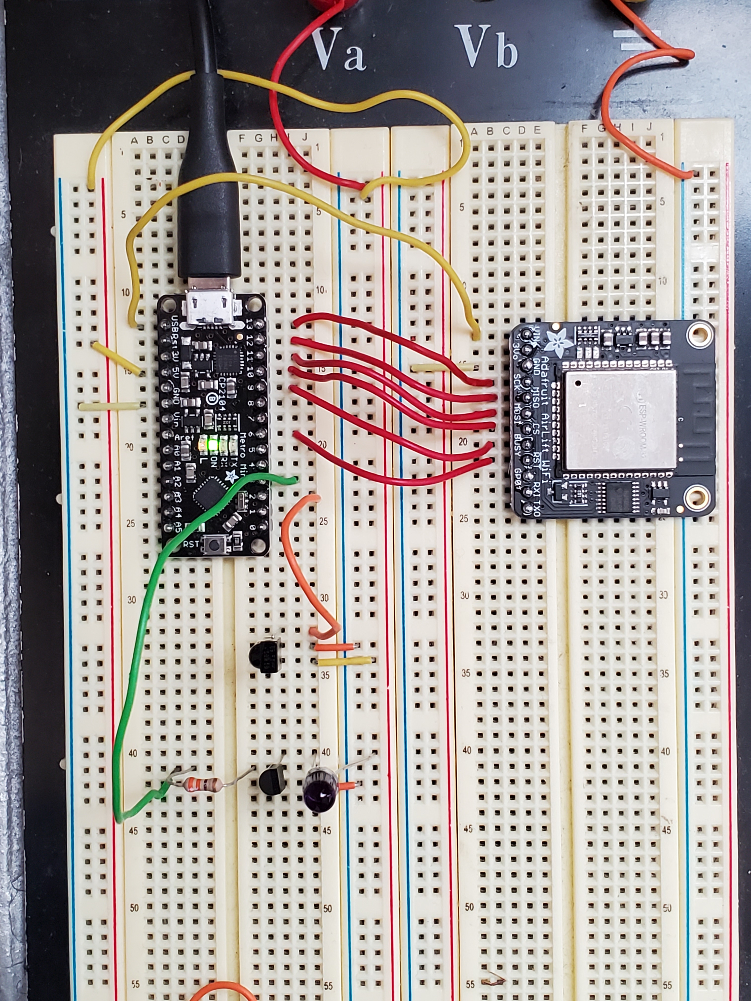
- Arduino Uno – the brains of the operation
- HD44780-based 2×16 LCD screen – for data display
- PEC11 Rotary Encoder – for user input
- PCF8523 Real Time Clock (RTC) – for accurate timekeeping
- 5V submersible water pump – this will actually go in the water source
- 5V relay module – to control the pump
- Screw potentiometer – to adjust LCD brightness.
Background
I started this project thinking I would measure soil moisture and release water automatically. There are plenty of kits online that sell cheap PCBs shaped like a tuning fork for this purpose. These act as a potentiometer with resistance varying with moisture. Unfortunately they’re just not very accurate and worse the exposed metal corrodes over time. Supposedly capacitive sensors are better in this regard but I realized measurement isn’t very necessary. All our houseplants are watered on a schedule anyways, so I just needed a way to automate that.
Concept of Operations
The user configures how often they want the plant watered and how much water to use. Settings are selected by turning the rotary encoder and confirmed with a push. These settings translate to a time and duration to run the pump for. I did some experiments to measure the flow through the pump and found it conveniently moves about 1oz of water every 1 second.


The internal oscillator on the Arduino board will lose several minutes per day. While this is not a big deal for our application, I decided to add a Real Time Clock (RTC) module to the build. Accuracy loss on this device is several seconds per month! The big advantage is that the RTC can generate an interrupt on a configurable interval (I chose 10 seconds) to wake the board up.
After settings are confirmed, the unit goes into sleep (SLEEP_MODE_PWR_DOWN) until the RTC interrupt fires. If it’s not time for watering yet the unit repeats the sleep cycle. In theory this should make it low power enough to run off a 9V battery, though in our installation we used a USB cable and wall wart for power.
The pump is submerged in a vase of water. When time for watering, a digital output pin from the Arduino trips a relay which powers on the pump for the required duration (using 1s = 1oz). After watering is complete, a timer is set for the next watering interval and the unit sleeps again.
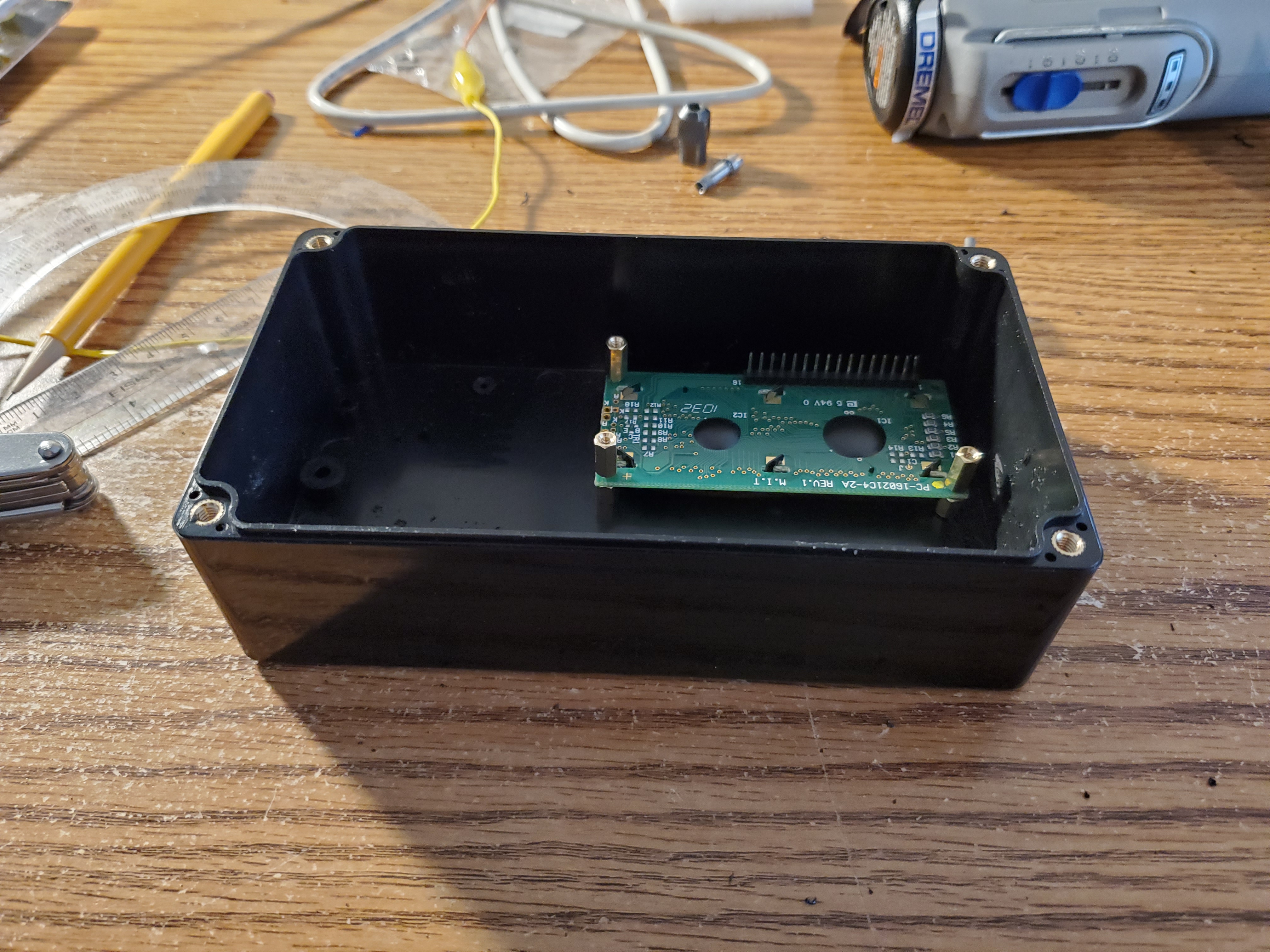
Wiring & Build

I house the electronics in a simple project box and made the cutouts by hand with my Dremel. Boards were mounted using screws and standoffs. Admittedly the hand drilling and screws aren’t aesthetically pleasing, but I wasn’t going for looks in this project. The relay didn’t have mounting holes, so I used double-sided Velcro to mount it to the side.


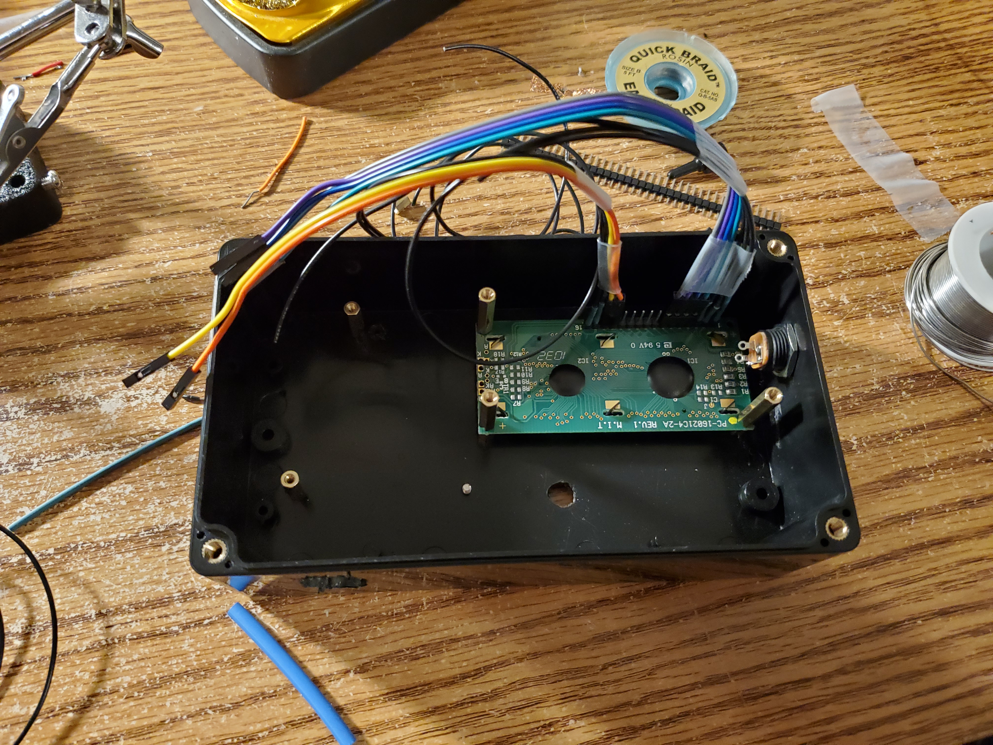
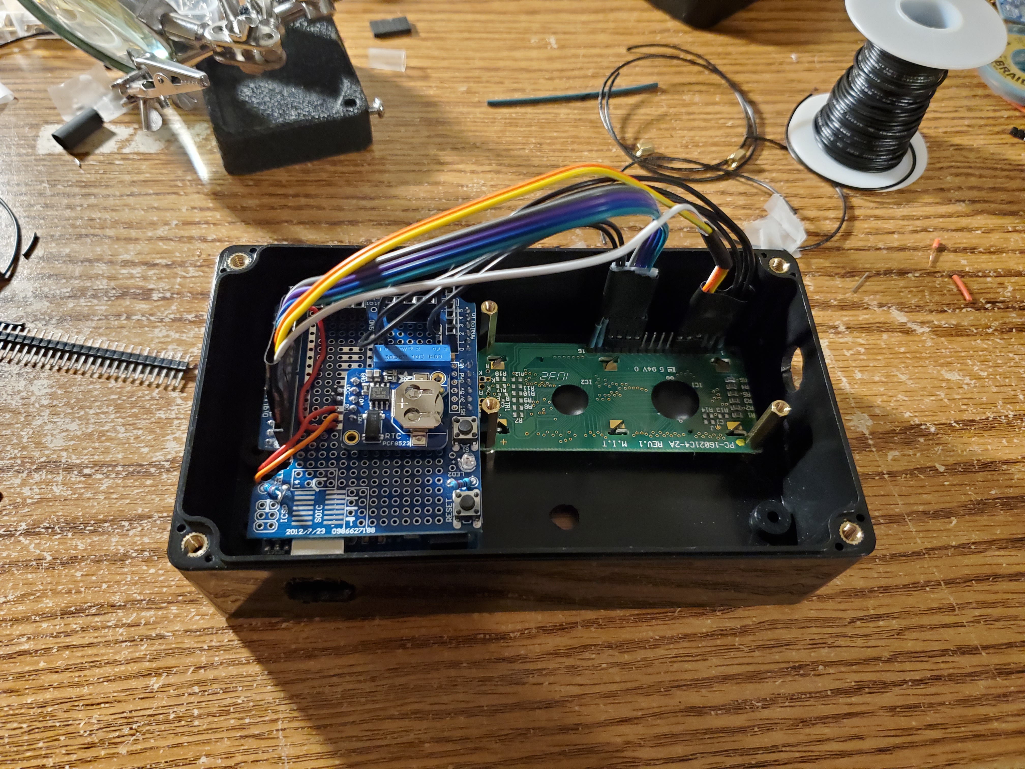
I used some Arduino-shaped perfboard (sometimes called a Proto Shield) to mount the RTC and potentiometer for LCD brightness adjustment. Since it was inside, the LCD wouldn’t be user adjustable, but I really just needed to put it at a good set point once. I didn’t have a full ribbon cable for the LCD which made the wiring messier than desired, but all the connections were made following the above diagram without issue.

I wanted the pump wired so that it could be disconnected to move easily. I soldered the leads of the pump itself into a barrel plug and fitted the side of the project box with a barrel connector. With that it was ready to go!

Code
The encoder knob was straightforward to work with using the encoder library. I found the knob quite sensitive so I adjusted the read logic to require four clicks to change a value.
int incrimentEncoder(int inc)
{
  long newPosition = enc.read();
  if (newPosition != oldPosition)
  {
    if ((newPosition-oldPosition)>=4)
    {
      oldPosition = newPosition;
      return inc;
    }
    else if ((oldPosition-newPosition)>=4)
    {
      oldPosition = newPosition;
      return -inc;
    }
  }
  return 0;
}
Settings were applied by pressing the encoder knob down, which was measured by a digital input (buttonPin). I just had to implement a simple debounce routine.
/*  Check state of rotary button
 *  Return TRUE if button has been pressed
 */
bool buttonPressed()
{

  // No press detected, by default
  bool returnState = false;

  // Get current reading
  int reading = digitalRead(buttonPin);

  // If the switch changed, due to noise or pressing:
  if (reading != lastButtonState)
  {
    // reset the debouncing timer
    lastDebounceTime = millis();
  }

  // Debounce
  if ((millis() - lastDebounceTime) > debounceDelay)
  {
    if (reading != buttonState)
    {
      buttonState = reading;

      // Push is low, so register if pushed
      if (buttonState == LOW)
      {
        returnState = true;
      }
    }
  }

  //Store variable
  lastButtonState = reading;
  return returnState;
}
The majority of the logic in the code has to do with moving through the screens to configure watering time and duration. The Liquid Crystal library helped here.
Finally, I needed to set up the sleep routines. This started by configuring the RTC in the setup routine, by using the RTC library.
  rtc.deconfigureAllTimers();
  rtc.enableCountdownTimer(PCF8523_FrequencySecond, 10);  // 10 seconds
An interrupt was attached to the 10 second timer from the RTC as well as the encoder button press, so the user could wake the unit up at any time.
void enableSleep()
{
  // Attach interrupts and make sure they have time to register before sleep
  attachInterrupt(digitalPinToInterrupt(sqwPin), timerIsr, FALLING);
  attachInterrupt(digitalPinToInterrupt(buttonPin), buttonIsr, FALLING);
  delay(100);

  timerFired = false;
  buttonFired = false;

  // sleep_mode() is a blocking call
  set_sleep_mode(SLEEP_MODE_PWR_DOWN);
  sleep_enable();
  sleep_mode();

  sleep_disable();
  detachInterrupt(digitalPinToInterrupt(sqwPin));
  detachInterrupt(digitalPinToInterrupt(buttonPin));
  Serial.println("morning.");
}
The variables timerFired and buttonFired are set in their respective interrupt service routines (ISRs) and checked in the main loop to take action. Each time the timer interrupt fires, we compare the current time against the time of the next watering and switch the relay on if it’s time to water.
void checkTimer()
{
  DateTime now = rtc.now();
  if (now > nextWatering)
  {
    Serial.println("WATERING");
    // Water now
    triggerRelay();
    delay(1000);
    lcd.begin(16, 2);
    lcd.clear();
    lcd.print("Done.");
    delay(1000);
    // Update timer for next watering interval
    setNextWatering();
  }
}
The full code is available on GitHub.
The Test
After some checkout tests, the setup was ready for primetime. We connected the pump output through a small section of tubing into the pot. After two weeks away, the Bird of Paradise was well-watered and doing great when we returned!